# Using the Workflow Designer
A workflow enables automated and repeated execution of a sequence of tasks, such as running a program, sending emails, uploading a file, running a transfer setting or batch, executing SQL scripts, and many others. To learn more about *Workflow Tasks*, click [here](https://documentation.astera.com/astera-data-stack-v8/workflows/creating-workflows-in-astera).
Let’s look at how we can use the features provided by the workflow designer to make the implementation and visualization of the job effortless.
## **Creating a New Workflow**
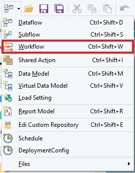
To create a new workflow, go to *File > New >* *Workflow* on the main menu. Alternatively, you can expand the *Create New Dataflow* dropdown icon on the main toolbar and select *Workflow*, as shown below.
## **Managing the Workflow Layout**
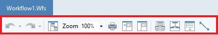
When the workflow designer opens up, you can see the workflow toolbar below the Workflow1 tab.
In the following sections, let’s discuss these features and their functions.
## **General Options**
* *Undo/Redo* – The workflow designer supports unlimited undo and redo capability. You can quickly undo/redo the last action done, or undo/redo several actions at once.
* *Auto Layout Diagram* – The *Auto Layout* feature allows you to arrange objects on the workflow improving its visual representation.
* *Zoom* – The *Zoom* feature helps you adjust the display size of the workflow. Additionally, you can select a custom zoom percentage by clicking on the Zoom % input box and typing in your desired value.
* *Print* – The *Print* feature allows you to print your created workflow.
* *Expand All* – The *Expand All* feature expands or enlarges the objects on the workflow improving the visual representation.
* *Collapse All* – The *Collapse All* feature closes or collapses the objects on the workflow, improving the visual representation and reducing clutter.
* *Auto-Size All* – The *Auto-Size All* feature resizes all the objects in a manner where all fields of the expanded nodes are visible and the empty area inside the object is cropped out.
* *Use Orthogonal Links* – The *Use Orthogonal Links* feature draws the link between objects in an orthogonal curve instead of a straight line.
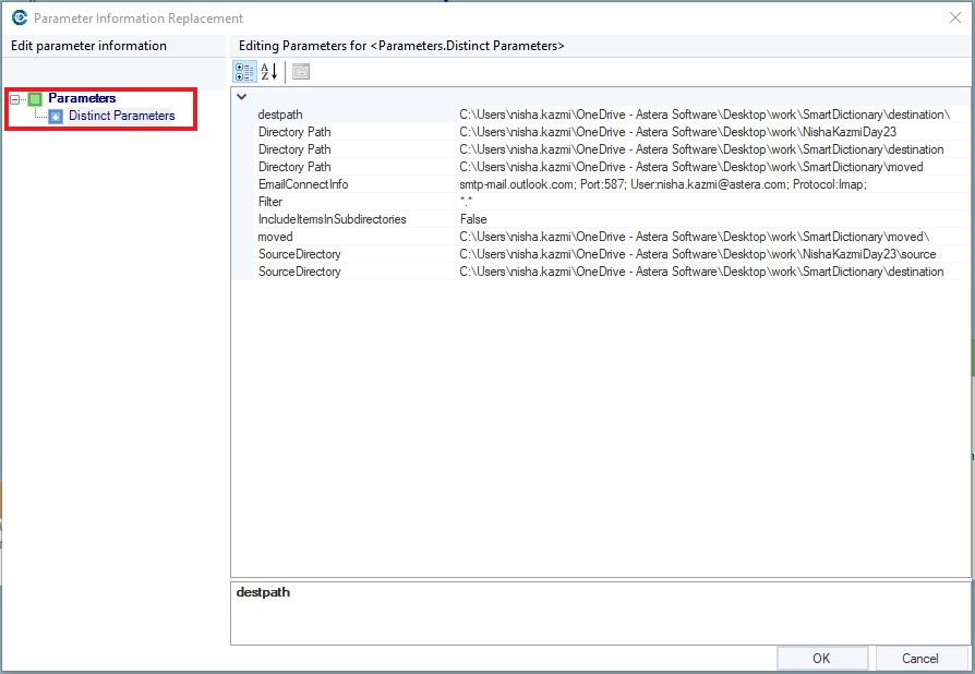
* *Replace Parameter Infos for All the Distinct Parameters* – This feature displays all the distinct directories and connections used in the objects available on the workflow designer.
To invoke this feature, click the *Replace Parameter Infos for All the Distinct Parameters* icon on the workflow toolbar. Alternatively, you can open the workflow menu and select this feature.
A workflow can be ported to run in any number of target environments. Hence, you need to change the parameter values depending on the current context in which the workflow runs. This feature can be used to change all the distinct parameters without individually visiting the objects.
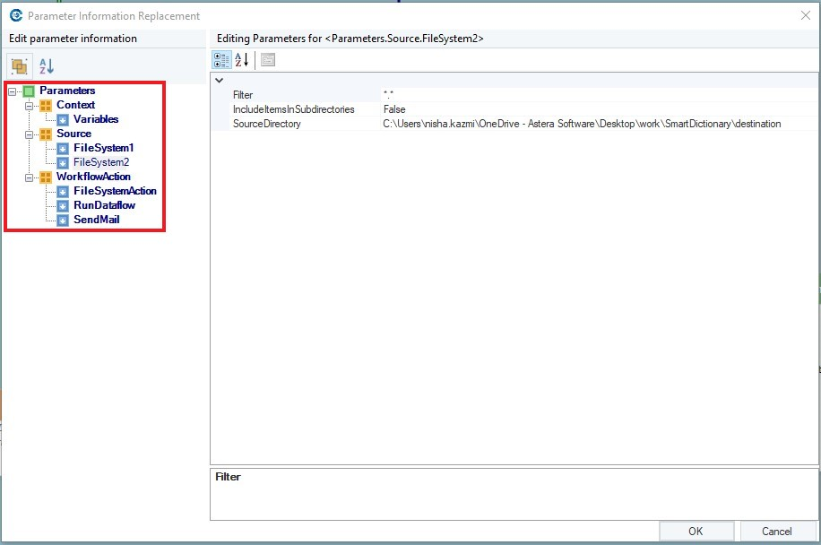
* *Replace Parameter Infos* *Individually* – This feature displays all the parameters that have been assigned to each object used in the workflow.
To invoke this feature, click the *Replace Parameter Infos Individually* icon on the workflow toolbar; you can open the workflow menu and select this feature.
This feature displays the objects that have been used in the workflow in a categorical structure – View by Category – and allows you to change the parameters by simply clicking and editing.
## **Linking Objects**
### **Ports**
Every object in the *Workflow Tasks* section of the toolbox has input and output ports when added to a workflow. These ports make it possible to connect an object to another object via links, creating the required workflow path.
The input port on an object allows you to connect it to an upstream object on the workflow. Conversely, the output port allows you to connect your object to a downstream object on the workflow. The downstream object represents a task that will be processed after the upstream object it is connected to has finished running.
{% hint style="info" %}
**Note:** There are some exceptions, such as the *Run Program* task, which may not require waiting for the program to exit.
{% endhint %}
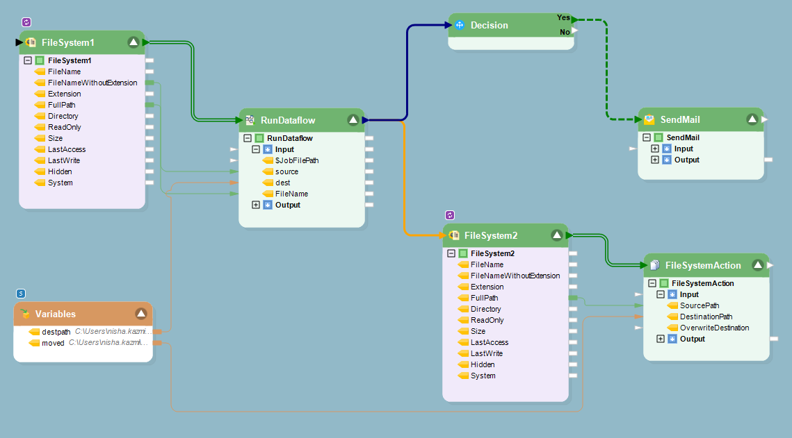
Here is a sample workflow that demonstrates the usage of input and output ports:
### **Links**
A link between two objects can be created by dragging the output port of the upstream object and dropping it on the input port of the downstream object.
To remove a link between two objects, right-click on the link and select *Delete* from the context menu.
{% hint style="info" %}
**Note:** It is also possible to connect multiple upstream objects to a single downstream object.
{% endhint %}
There are three types of links in a workflow:
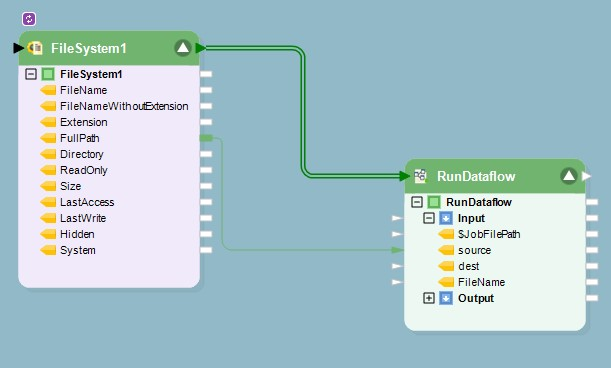
1. *Double Lined*: Link from a *Source object* to a workflow task object. This line will only appear if you are using the source as a loop.
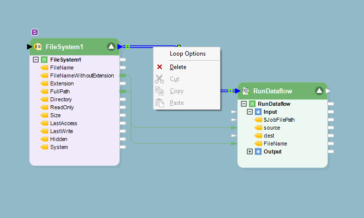
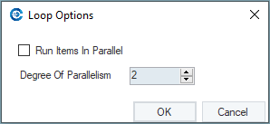
Right-clicking on the *Double Lined Link* and selecting the *Loop Options* will show you the screen where you can choose the *Degree of Parallelism*.
*The Degree of Parallelism* indicates the number of concurrent supply of files. For example, if you set it to 2, two files go through the *Run Dataflow* Task simultaneously.
2. *Single* *Lined*: Link from a workflow task object to any other object.
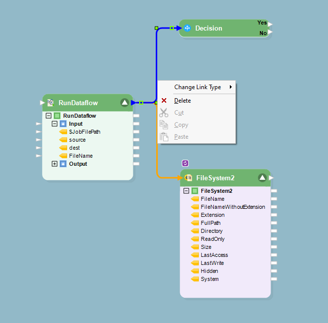
To change the link type, right-click on the link and select *Change Link Type*.
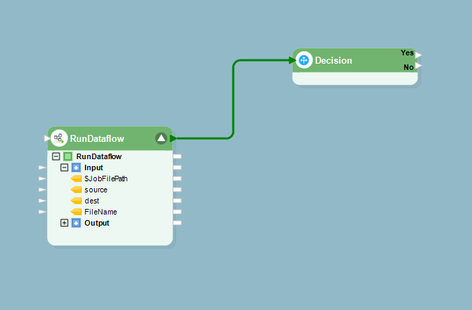
* By default, a *Normal* link is created between an upstream and a downstream object. Normal link means that the downstream object will be processed in the event of a successful completion of the upstream object to which it is connected. *Normal* links are displayed in green.
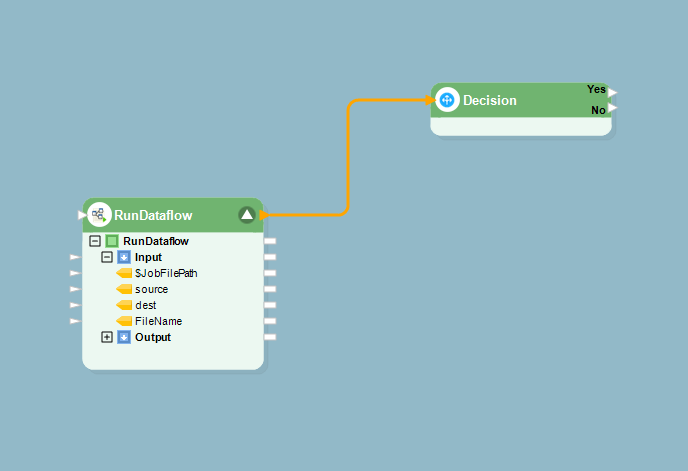
* In contrast, an *Error* link means that the downstream object will be processed only in the event of a failed (error) status of the upstream object to which it is connected. Error *Links* are displayed in orange.
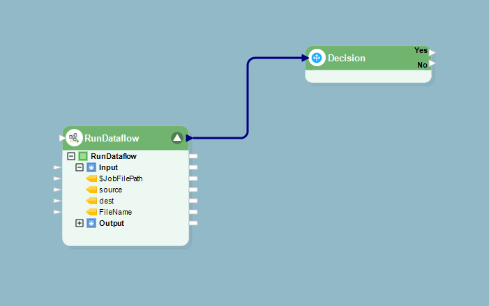
* In addition, an *Always* link means that the downstream object will be processed irrespective of the status of the upstream object to which it is connected. *Always Links* are displayed in blue.
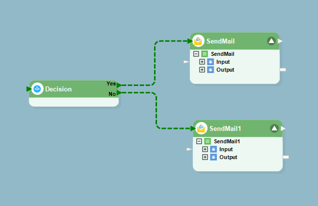
3. *Dotted Lined*: Link from a *Decision* workflow task object to other objects.
This is how various features of the workflow toolbar can be utilized to abridge the time and effort needed for the creation of complex tasks in a workflow in Astera.